

Authors:
(1) Mehdi Naderi;
(2) Markos Papageorgiou;
(3) Dimitrios Troullinos;
(4) Iasson Karafyllis;
(5) Ioannis Papamichail.
Table of Links
The Nonlinear Feedback Control
OD Corridors and Desired Orientations
Boundary and Safety Controllers
Appendix A: Collision Detection
Appendix B: Transformed ISO-Distance curves
Appendix D: Safety Controller Details
Appendix E: Controller Parameters
APPENDIX B: TRANSFORMED ISO-DISTANCE CURVES
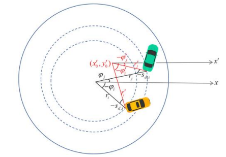
For the iso-distance curve transformation to align with the desired orientation, new polar coordinates are defined whose origin is found by crossing two lines perpendicular to the vehicles’ rear axles, while having the ego vehicle’s desired deviation from the circular angle. This implies that the coordinates are different for each pair of vehicles. The lines’ equations, according to Fig. 20, can be written as
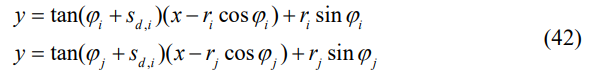
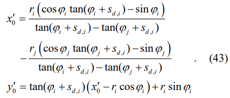
Note that each vehicle projects other vehicles on its own coordinates; therefore, in both equations of (42), the desired orientation of vehicle i is taken into account. Intersecting above
equations gives the centre of new coordinates as
Then, the radius and angle of each vehicle in the new coordinates is calculated by
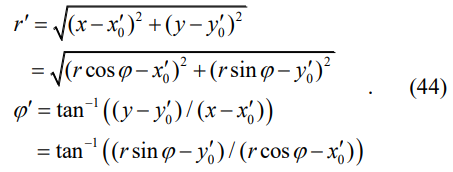
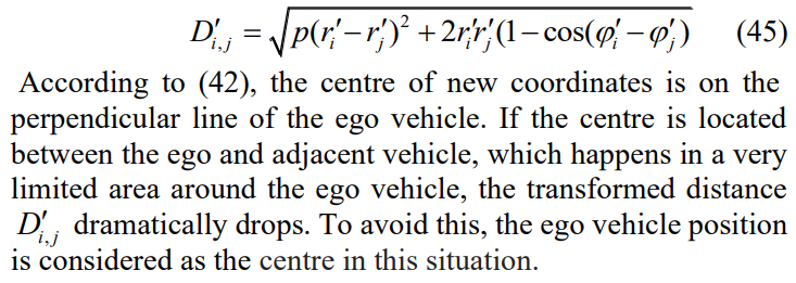
Furthermore, the distance in the new coordinates is
This paper is available on arxiv under CC 4.0 license.